Rear Upright
Design and Analysis
This is the rear upright I designed for the CWRU Motorsports Baja SAE team. It fills the role of integrating the desired suspension geometry with the load bearing driveshafts while constraining the wheel along its path through suspension travel
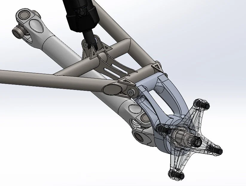
Upright in rear outboard assembly with upper suspension arm and driveshaft (which also acts as the lower suspension arm)
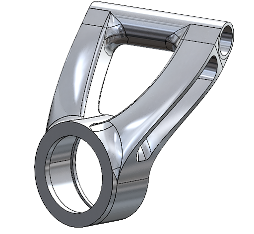
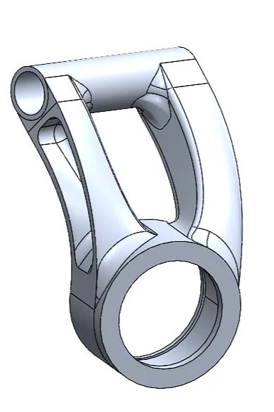
The upright geometry is designed based on suspension geometry that defines the bearing position of the rear outboard spindle relative to the end of the upper suspension arm pivot. The beams connecting the bearing bore to the pivot tube are designed using surfaces to generate ideal geometry to balance strength to weight. All features in the design were optimized to be manufactured in a 3 + 1 axis mill.

Part level Finite Element Analysis on the rear upright using remote loads positioned at a max loading condition. The load was measured by a wheel force transducer on the rear wheel of the car during a full speed drop test to simulate a worst case scenario loading condition.
Manufacturing
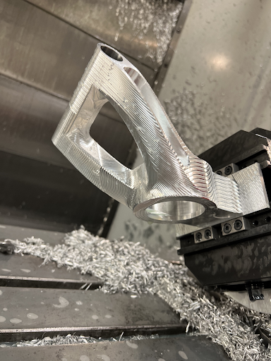
Rear upright fixtured in 4th axis of HAAS CNC Mill with only 1/8 inch of fixture height to allow machining entire part in effectively 1 fixture
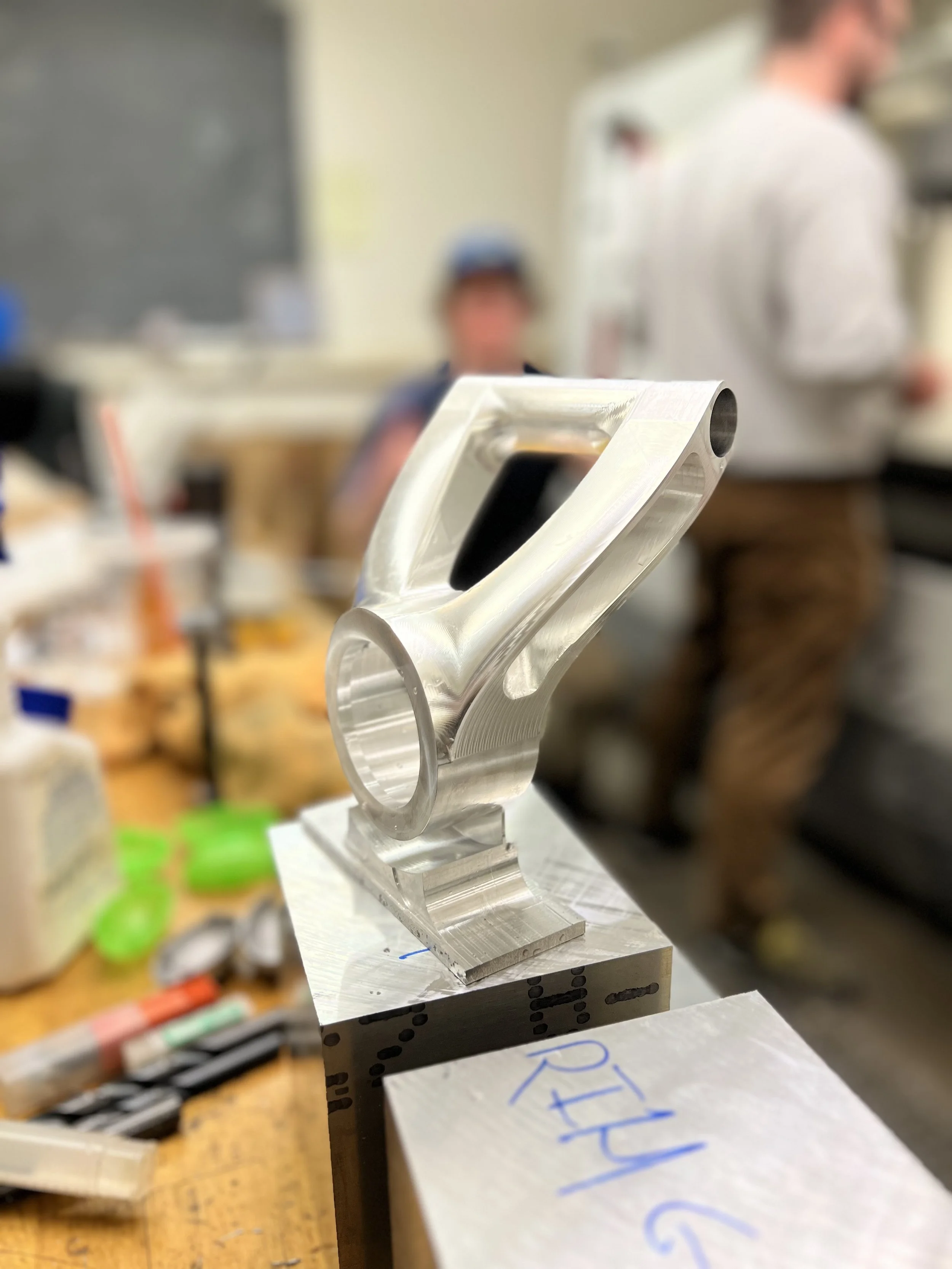
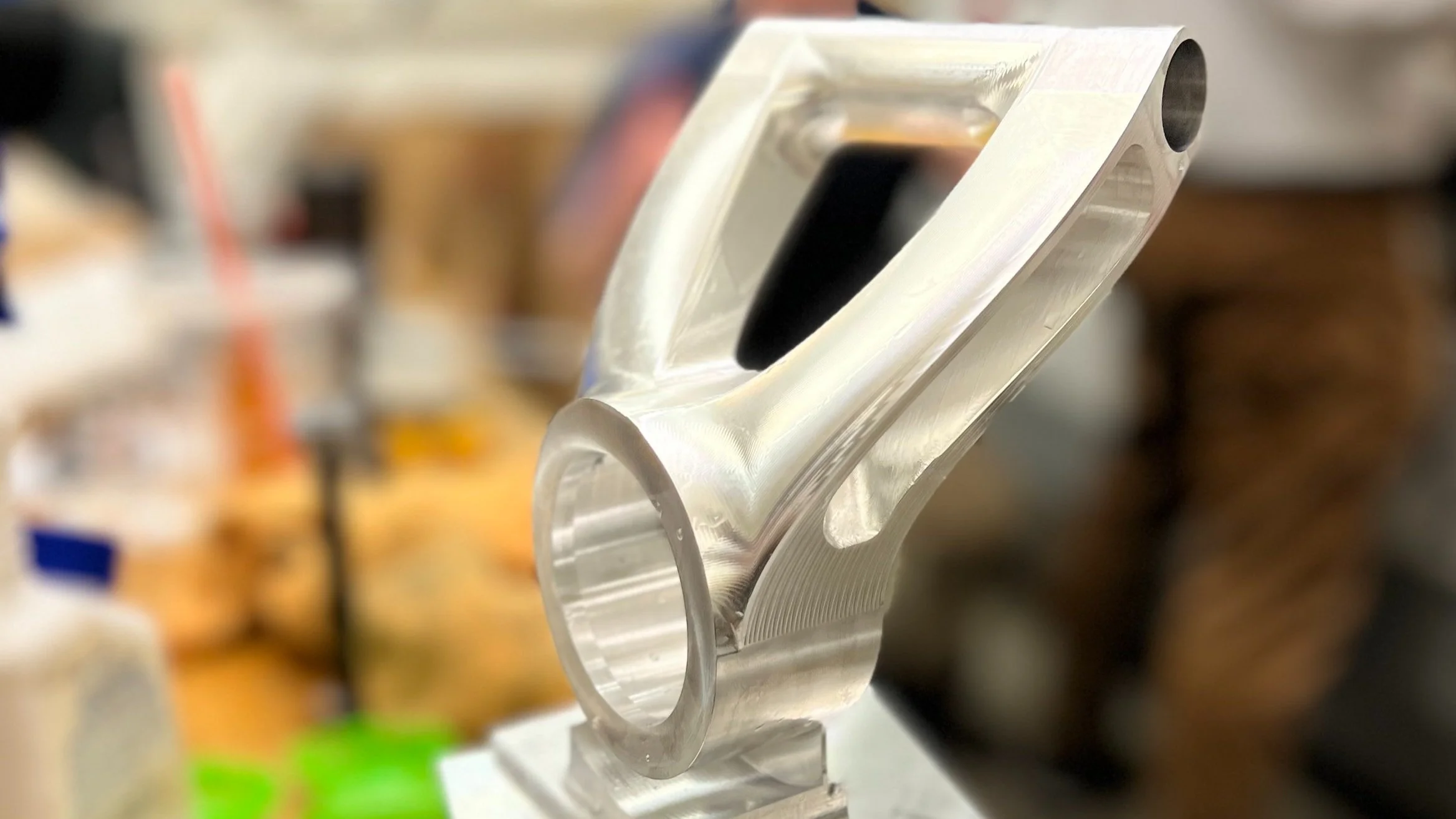
Finished upright after all CNC operations are complete with a 1/16 inch tab left for work holding. (The upright is sitting on the initial stock it was made out of)
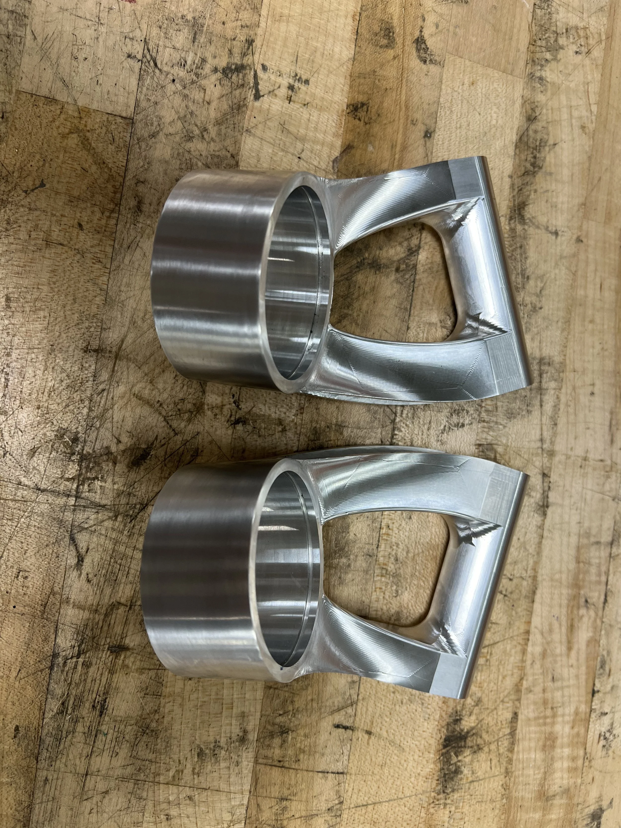
Fully finished uprights
All CAM and machining credit goes to Brendan Flanagan