Continuously
Variable
Transmission
Design
This is my first attempt at designing the primary clutch of the CVT transmission for the CWRU Motorsports Baja SAE car. It is a backwards compatible, drop-in replacement for an off the shelf system designed to address the pain points of the previous solution while improving performance under acceleration and up hills while maintaining performance over an extended period of time

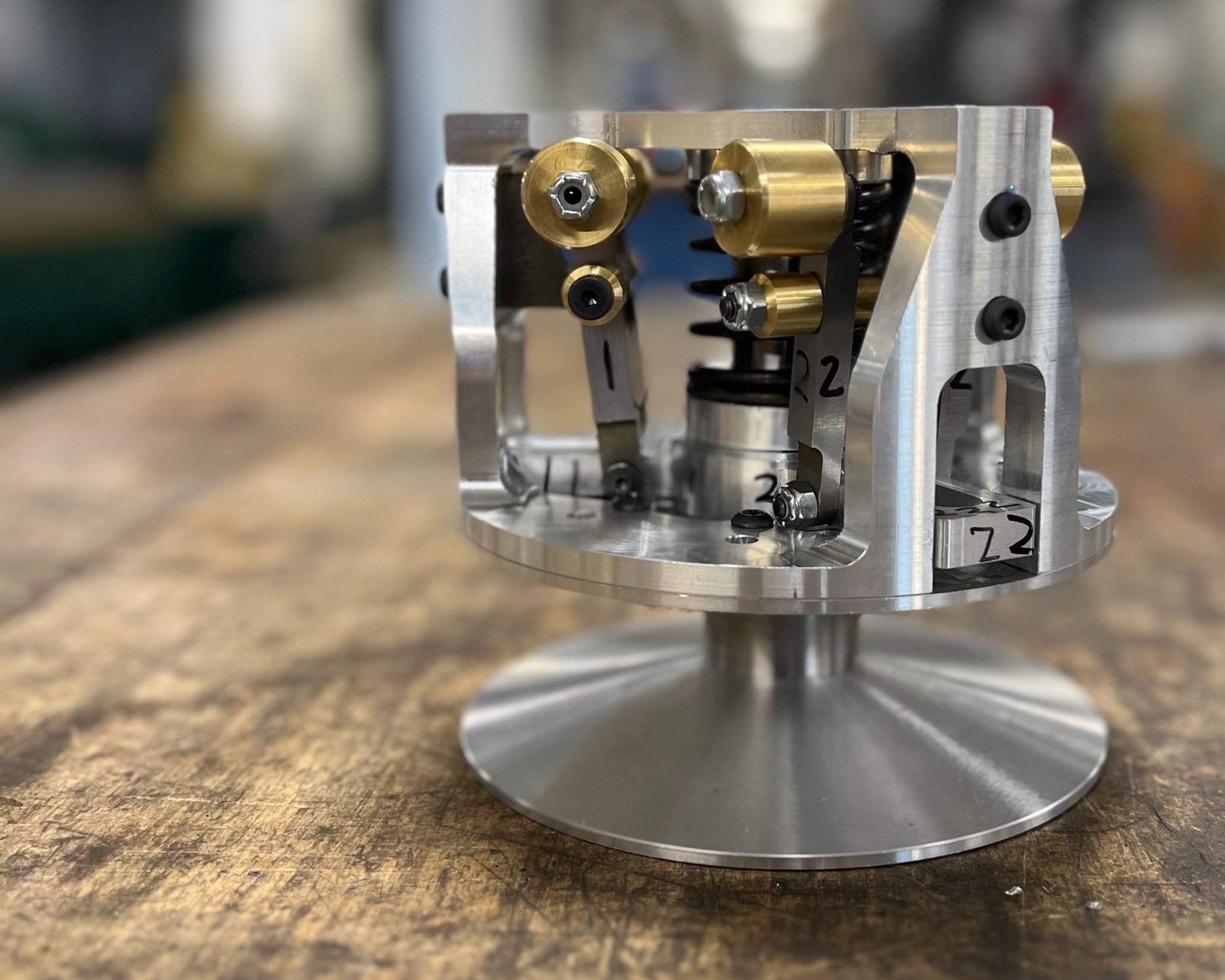
Custom CVT primary with off-the-shelf secondary

Early version of CVT Primary that evolved after running analysis on the individual components.
Analysis
I ran hand calculations and SOLIDWORKS Finite Element Analysis on every part in the assembly to validate the system to survive 500000 peak loading fatigue cycles.


Initial free body diagram to determine force balance and geometry of flyweights cam follower and cams; plus, equation derived from free body diagram to estimate mass needed on flyweights to shift are desired RPM

Part level simulation of floating shave with forces from cage transferred through to simulated contact area on floating sheave and using the belt as a fixture

Assembly level simulation with both cage and floating sheave (with other components that mate to them) to more accurately simulate fixtures and contacts stresses on both components
Assembly level centrifugal simulation on spider and flyweight assembly to gage max stress and deflection on parts by spinning at 3800 RPM

Part level deflection analysis on CVT cage. The cage sees the most number (7) and largest magnitude of forces (~2800 N)

Part level simulation on cage to specified stress limit to hit fatigue cycle requirement. Part is fixtured by using the simulated contact area due to the bolt pressure on the mating faces between cage and floating sheave as fixtures

Harmonic simulation at fully shifted state to verify that the 1st harmonic mode (@ ~14400 RPM) is above the peak RPM of the engine (~3800 RPM)

Assembly level centrifugal simulation (seen above) with flyweight arm isolated to view the high stress areas on the bores due to cantilevered weights
Manufacturing
After the design was finalized and reviewed, the process for manufacturing each part of the transmission started using manual lathes, a CNC mill and wire EDM


that’s me!


All CAM credit for CNC Mill parts goes to Brendan Flanagan
Assembly
& Testing

First time checking if threads on mating parts fit together

First assembly of primary clutch

First time test fitting primary clutch in retired car for testing and tuning

First test run at engine idle without belt

Shift curve derived from tracking primary RPM, secondary RPM and front wheel speed and then generated in MATLAB; the curve is engine RPM vs vehicle speed and describes what RPM the CVT is shifting through its range
Winning acceleration run at BAJA SAE California
